Schritt 4: Milling

Since we wanted to carry out the milling work on the machines in our university, we also had to create the program for the control of the milling machine ourselves. We have defined suitable milling operations in the manufacturing module of our CAD system:

  1. Roughing with an end mill

  2. Finishing with a ball mill
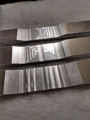
We milled the bars with very low infeeds and feeds at high spindle speeds. As a result, both the tool and workpiece load and the heat input into the bar are very low.


The milling preparation shown in the simulation is usually carried out by the company that does the milling work. It is usually sufficient to give a corresponding company a digital data record (Step, IGES) of the bars and the accuracy requirements.
There are large numbers of qualified companies, at least in Germany.

 
We tried out different milling strategies, whereby the forward and backward movement across the bar turned out to be the most suitable because it was the fastest.


Before anodizing, we easily removed the small burrs along the milling marks with a belt sander. The subsequent control of the frequencies brought an excellent agreement with the previously simulated values.

Since we were initially unsure about the quality of our simulation, we kept an allowance of 0.2 mm for the arithmetic target geometry for the milling processes at the tuning points. We then had to work these away after anodizing during fine tuning. In the next set of bars, we omit this oversize.

We underestimated the problem of drilling holes for the cords. Unfortunately there was no 5-axis milling machine available. Therefore, we made the holes by hand on a normal column drill. In most cases this has gotten pretty neat, but in some cases it hasn't either. Inaccurate drilling angles lead to tension in the cord. This hinders the bar from free vibration and thus reduces the sustain.

If the entire milling work, including the bores, cannot be carried out with a 5-axis milling machine, the following procedure is recommended: