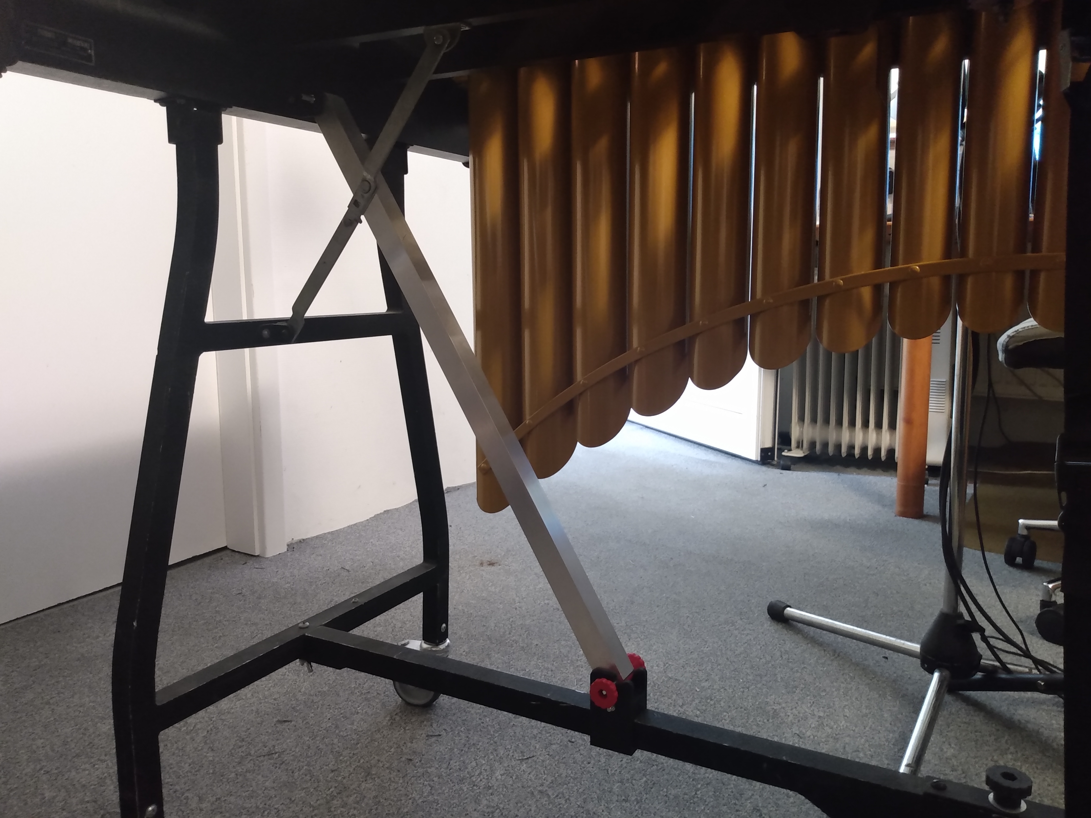
Frame stabilization for older M55 vibraphones
I have here two simple and inexpensive, but very effective
and easy to realize solutions for frame stiffeners on old Musser M55 vibraphone
frames. All you need are a few easy-to-source 3D printed parts, two pieces of
aluminum square tubing and a few nuts and bolts.
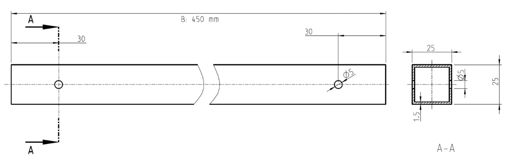
Drill a 5.0 mm diameter hole 30 mm from the cut edge at both ends of the 25 mm x
25 mm x 1.5 mm aluminum square profiles (commercially available DIY store
goods).
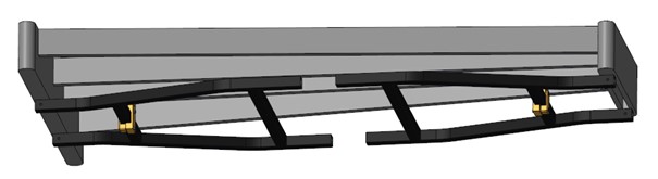
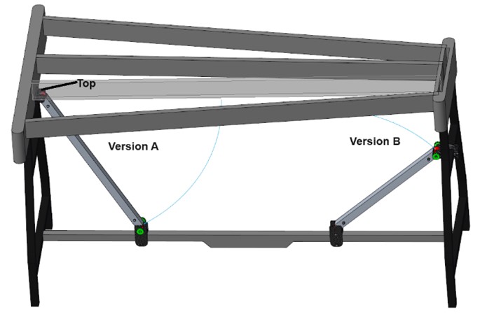
Version A is more stable and more
convenient for dismantled frame transportation, as the outriggers can be folded
in with the side parts.
Download the 3D
printed parts for
version A here.
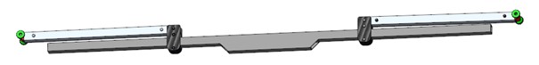
Version B does not require any
modifications to the original vibraphone frame, as all components are simply
clamped.
Download the 3D
printed parts for
version
B here.
The structure and function of both variants are shown in the following illustrations.
Version A
Tube length square tube: 580 mm
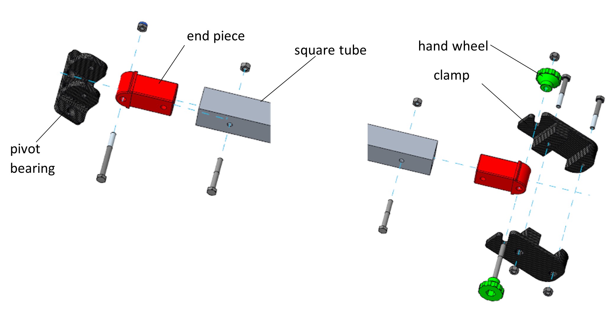
For version A, the two clamp half shells
are placed on the pedal bar and lightly screwed together (ISO 4014 M5x35 and nut
ISO 4032-M5) so that the clamp can still be moved on the pedal bar. The two end
pieces are then inserted into the tube and screwed together with ISO 4014-M5x45
screws and ISO 4032-M5 nuts. On one side, the pivot bearing is screwed in place
with a screw ISO 4014-M5x45 and a nut with clamping part ISO 10511 so that it
can rotate easily but is free of play. On the other side of the cross strut, a
screw ISO 4014-M5x50 is inserted through the first handwheel, then through the
free end piece and further through the second handwheel. Then screw on another
ISO 4032-M5 nut.
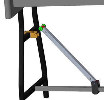
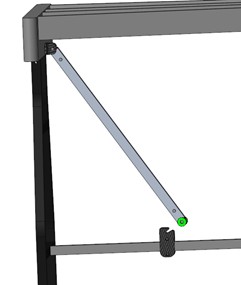
To mount the pre-assembled cross strut to the frame, the side with the two
handwheels is inserted into the groove of the clamp and lightly fixed in place
by tightening the handwheels. By moving the clamp on the pedal beam, the
position is changed until the lower edge of the pivot bearing is flush with the
lower edge of the wooden frame. The pivot bearing is now mounted in the frame
using wood screws.
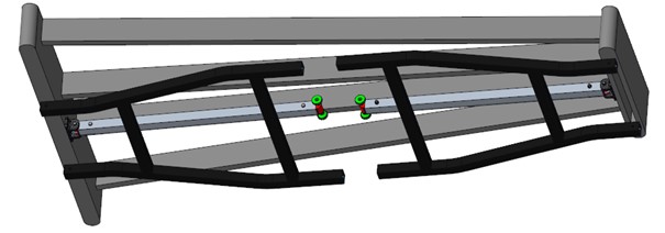
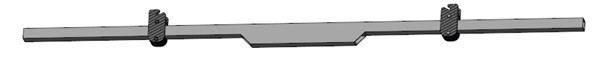
Version B
Tube length square tube: 450 mm
For version B,
the two clamp half shells are placed on the pedal bar and lightly screwed
together (ISO 4014 M5x35 and nut ISO 4032-M5) so that the clamp can still be
moved on the pedal bar. The two end pieces are then inserted into the tube and
screwed together with ISO 4014-M5x45 bolts and ISO 4032-M5 nuts. One side of the
cross strut is screwed into the clamp using a screw ISO 4014-M5x45 and a nut
with clamping part ISO 10511 so that it can be easily rotated but is free of
play. On the other side of the cross strut, a screw ISO 4014-M5x50 is inserted
through the first handwheel, then through the free end piece and further through
the second handwheel. Another ISO 4032-M5 nut is then screwed on.
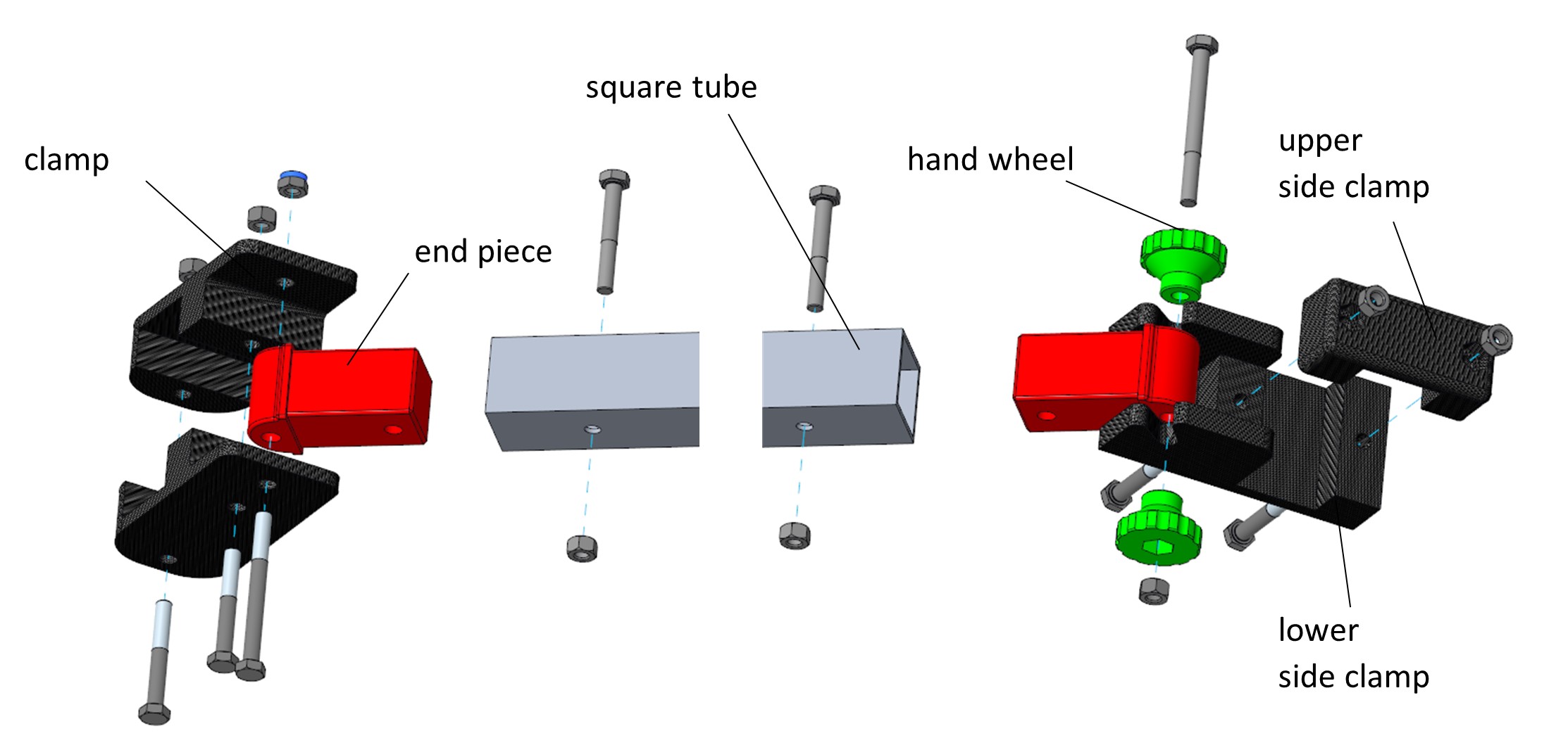
The lower and upper side clamps are placed on the crossbar of the vibraphone
frame and screwed together with two M5x35 screws and an M5 nut so that the side
clamp can still be moved.
The exact position of both clamps is determined by inserting the pre-assembled
cross brace into the groove of the side clamp and fixed by tightening the
screws.